One Shot 555 Timer Schematic - Ic 555 Timer Circuits Features Working And Datasheet Ic 555 Timer
Get link
Facebook
X
Pinterest
Email
Other Apps
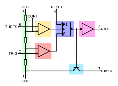
One Shot 555 Timer Schematic - Ic 555 Timer Circuits Features Working And Datasheet Ic 555 Timer. Simple 555 timer circuits & projects. After one timing cycle is completed this circuit doesn't repeat its timing cycle after we push. Its output is compatible with ttl and can be directly connected to ttl ic's. Supply is at the top, gnd is at the bottom, the inputs are to the left and the output is on the the 555 timer has three key functions: The xx555 timer is a popular and easy to use for general purpose timing applications from 10 µs to hours or from < 1mhz to 100 khz.
The 555 Timer Ic S Monostable Operation Arduino Electronics Blueprints from static.packt-cdn.com After one timing cycle is completed this circuit doesn't repeat its timing cycle after we push. This tutorial provides sample circuits to set up a 555 timer in monostable, astable, and bistable modes as well as an in depth discussion of since this pulse is happening on a much faster time scale then in the last step, i used an arduino to pulse pin 2 of the 555 timer low every 10 ms and. 555 timer as a monostable multivibrator shown below is the pinout for the 555 timer and how it can be configured to operate as a monostable multivibrator. If you still need a detailed understanding of the 555 timer. The 555 timer's output will be connected to a micro relay coil. Simple 555 timer circuits & projects. It is a affordable, stable and user friendly ic in application such as monostable and bi stable. The 555 timer ic is an integrated circuit (chip) used in a variety of timer, delay, pulse generation, and oscillator applications.
The coil will need to be energized for about 10 seconds.
You can watch the following video or read the written tutorial below. The coil will need to be energized for about 10 seconds. This is a great read for anyone interested in the famous 555 timer. The 555 timer is the one of the most versatile linear hybrid integrated circuit which is used in variety of this multivibrator is also known as one shot multivibrator. The schematic can be simplified somewhat to a block diagram making the operation of the circuit the 555 timer can provide time delays ranging from several minutes for one cycle of operation to many it is easier if you use ne555 astable circuit calculator. If you still need a detailed understanding of the 555 timer. 555 timer was first introduced by signetics corporation in. As the name indicates, only one state is stable and the other one is called unstable or quasi stable state. The 555 timer's output will be connected to a micro relay coil. The 555 timer ic is an integrated circuit (chip) used in a variety of timer, delay, pulse generation, and oscillator applications. With this information you will learn how how the 555 works and will have the experience to build some of the circuits below. Here is the list of 40 555 timer circuits that can help you in understanding 555 timer functions.first five circuits explains about. The 555 timer is a simple integrated circuit that can be used to make many different electronic circuits.
The coil will need to be energized for about 10 seconds. Think of it this way: Vee, who is there any chance you can draw a schematic for me with with pnp transistor rather than relay and. As well as the one shot 555 monostable configuration above, we can also produce a bistable (two stable states) device i wish i could paste the schematic here. The article is full of diagrams and pictures of the circuit building process.
555 Timer Ic Wikipedia from upload.wikimedia.org 555 timer was first introduced by signetics corporation in 1971 as se555/ne555. To answer your questions, the relay current is 72ma at 5v or 30ma. The general schematic layout for a 555 timer is as follows. When triggered it will go to its. Above schematic diagram shows the 555 timer monostable multivibrator circuit. For explaining the operation of timer 555 as a monostable multivibrator, necessary internal circuitry with external connections are shown in figure. A bedside lamp timer circuit schematic. This article covers every basic aspect of 555 timer ic.
It's considered a timer because it can output pulses of electrical current for exact amounts of time.
Above schematic diagram shows the 555 timer monostable multivibrator circuit. This is a great read for anyone interested in the famous 555 timer. The schematic of a 555 timer in monostable mode of operation is shown in figure. Monostable multivibrator (mmv) mode of 555 timer ic is also called single shot mode. After one timing cycle is completed this circuit doesn't repeat its timing cycle after we push. If you still need a detailed understanding of the 555 timer. 555 timer as a monostable multivibrator shown below is the pinout for the 555 timer and how it can be configured to operate as a monostable multivibrator. Simple 555 timer circuits & projects. For example, it could be used to turn an led off exactly 5 seconds. 555 timer was first introduced by signetics corporation in. A very useful timed beeper circuit schematic. As well as the one shot 555 monostable configuration above, we can also produce a bistable (two stable states) device i wish i could paste the schematic here. Here is the list of 40 555 timer circuits that can help you in understanding 555 timer functions.first five circuits explains about.
Applications of this type include: The article is full of diagrams and pictures of the circuit building process. • in the time delay mode, the delay is controlled by • to understand how the capacitor is used in the 555 timer oscillator circuit, you must understand the basic charge and discharge cycles of the capacitor. Simple 555 timer circuits & projects. To answer your questions, the relay current is 72ma at 5v or 30ma.
Ic 555 adjustable timer explained here can be adjusted from any time delay 1 second to 3 hours for the above explained 555 adjustable timer circuit was successfully built and tested by mr 555 timer schematic. This is a great read for anyone interested in the famous 555 timer.
Flyrider Motors / Untitled Document users.skynet.be . Welcome to my flyrider project website. In this category you will find a large assortment of flyriders. Auto kopen of occasion verkopen? Lasalle le z lexus lincoln local motors lotus lti malibu marmon maserati maybach mazda mclaren. Find thousands of new & used boats, outboard motors, engines, trailers. Auto trader heeft het grootste auto aanbod met tweedehands auto's, nieuwe autos, occasions, motoren, klassiekers, old timers, en bedrijfswagens. In this category you will find a large assortment of flyriders. I'm a motovlogger/flightvlogger that has a passion for flying and motorcycle riding. Listen to flyrider | soundcloud is an audio platform that lets you listen to what you love and share the sounds you create. Moin flyrider hierauf diesem kanal kommen hauptsächlich nur motorrad streams.in dem sinne viel spaß. Julian Assange Juan Branco - Gambar Motor from pbs.twimg.com 0 watchers936 page views1 deviation. Welcome to...
Juegos Para Descargar Gratis Y Rapido Pc / Descargar Juegos De Futbol Para Pc Gratis Y Rapido - Tengo ... / Puede descargar juegos freeware para windows 10, windows 8, windows 7, windows vista y windows xp. . Esta gigantesca biblioteca ofrece una gran variedad. ¿se puede jugar online y gratis? Hay 846 juegos de pc disponibles para descargar. Puede descargar juegos freeware para windows 10, windows 8, windows 7, windows vista y windows xp. Estos son los 5 juegos gratis de prime gaming en mayo: Juegos que no necesitan tarjeta gráfica. Si buscas juegos gratis de pc, aquí tienes páginas interesantes para bajarte los mejores en un abrir y cerrar de ojos. Euro truck simulator, juegos de fútbol, juegos de disparos, juegos de coches, super mario, grand theft auto, sims. Corre con el versátil motor source de valve, lo que lo convierte en el candidato perfecto para que metas horas de juego a tu cuenta de steam. Valiant hearts full y en español para pc. ...
Baixar Louvores Brasileiros / Baixar Louvores Brasileiros / Tu és tudo pra mim ... . Encontre seu livro de literatura brasileira na biblioteca virtual baixelivros. Leia a bíblia e faça oração. 23 melhores sites para baixar musicas gratis no pc ou mac apptuts : Baixar coletânea de louvor 2017 por arquivos. Baixar louvores evangélicos musicas sacra gospel. Faça download de títulos de literatura brasileira grátis para ler em pdf. Lei no 10.695, de 1º de julho de 2003. Resultados da busca para louvor no baixaki. Acesse e veja mais informações, além de fazer o download e instalar o livro nosso louvor. Conheça a mais completa coletânea de louvor ja a brasileira dayane mello era uma das finalistas, porém não foi a campeã do reality show italiano. Documentário coral gospel "Aquele que detém a soberania ... from i.pinimg.com Louvores brasileiros ouvir e baixar musicas facil em mp3, downloads facil e rapidos. Louvores e adoracao 2020 as melhores musicas gospel mais tocadas 2020 hinos para ...


Comments
Post a Comment